Offset
In-Plane Membrane Tensiometer
By Rick Wagner, 2004
1 Abstract
A new instrument for measuring membrane tension in two dimensions is proposed. The instrument uses two accelerometers, sensitive to the membrane in-plane directions, but mounted offset from the membrane to that they measure two orthogonal rotational oscillations. Membrane tension is a computed function of the measured resonant frequencies.
2 Introduction
The tension in a membrane has two components, the vector sum of which is the resultant tension. One way to measure the tension in the membrane is to apply a known normal force to the membrane and observe the resulting deflection, which is the method used in tuning drums for musical performance. However, the “drum dial” method does not distinguish between or resolve the component tensions.
Other approaches that have been tried in the past at NGST include membrane tension measurement from gravity loading [3] and membrane tension measurement with a distributed weight.[4] With the gravity loading technique, photogrammetric surveys with reflective targets are performed with the membrane horizontal and again with the membrane horizontal and inverted. The tensile components can then be inferred from the shape information obtained photogrammetrically. However, inferring the tension in the long direction of a rectangular shaped membrane is problematic and inferring tensions in non-rectangular membranes is even more so.
The distributed weight technique provides more accurate tension measurement than the plain gravity loading method, but it similarly requires that the membrane be horizontal and it requires visual access to the membrane.
It has been suggested that laser speckle pattern interferometry might be used for differential membrane tension measurement. However, the method only measures changes in tension within a given setup. It would not be useful to measure absolute tension or changes in membrane configuration after exposure to simulated space environments.
This paper describes a new device that distinguishes tension in a membrane by its effect on the mechanical resonance in the membrane in two orthogonal directions. The device resolves directional resonances in a membrane under tension. A model of such a device is shown below in Figure 1 and Figure 2.
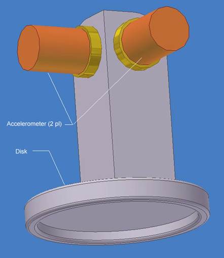
Figure 1: Offset in-plane membrane tensiometer. The disk is bonded or magnetically clamped to the membrane. The two accelerometers are sensitive to the in-plane directions, but are mounted at an offset distance from the membrane.
The device consists of a lightweight disk to which is mounted a stand-off on which two accelerometers are mounted. The two accelerometers are oriented with their sensitive axes in the in-plane directions, normal to each other. They are sized to be sensitive to the vibration amplitudes and frequencies anticipated for the particular application. The vibration excitation source can be from impulse (tapping on the membrane either in-plane or out-of-plane) or from a noise source, such as acoustically transmitted amplified noise.
The accelerometers will not be sensitive to out-of-plane motions so those vibrations will not be included in instrument response. Out-of-plane motions will also be damped in an air environment.
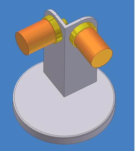
Figure 2: Another view of the device. Lead wires for the accelerometers are not shown.
3 Mathematical Description
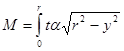
Consider a side view of a disk bonded to a tight membrane. If the disk is disturbed in rotation about an axis in the plane of the membrane, then the rotation of the disk through angle a will result in an out-of-plane motion h at some distance x from the axis of rotation, as shown below in Figure 3.
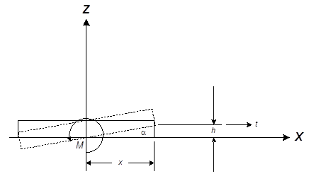
Figure 3: Side view of a disk bonded to a membrane under tension t (lb/in). If the disk is disturbed in rotation about the Y axis through angle a, then the disturbing moment M is equal to the integral of thx dy.
The disturbing moment M is the result of the integration of the tension along the edges of the disk, as shown below in Figure 4.
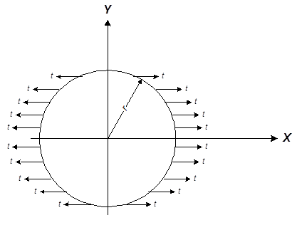
Figure 4: X-axis tension acts on every point on the circumference of the disk.
If we consider only the first quadrant of the disk we have the definite integral
 dy (1)
where t is the per-unit tension. Taking advantage of the small angle assumption
![]() (2)
(2)
and
![]() (3)
(3)
Combining (1), (2), and (3) gives
 dy (4)
which is equivalent to (see reference [2], table of integrals)
![]() (5)
(5)
evaluated at 0 and r, which is
![]() (6)
(6)
The natural frequency f of the rotational oscillator [1] is
![]() (7)
(7)
where
![]() (8)
(8)
and
![]() (9)
(9)
Substituting for p in equation (7) gives:
![]() (10)
(10)
where I is the mass moment of inertia of the device.
Setting a membrane tension t = 1 lb/in. = 12 lb/ft with a one-inch diameter disk with r = 0.5 in. @ 0.042 ft and I = 0.0001, for example, gives a natural frequency of 24 hz. The frequency is proportional to the square root of the tension and is inversely proportional to the square root of the mass moment of inertia (which dominates the radius term). If lower tensions need to be measured, or higher frequency response is desired, smaller devices can be fabricated.
4 Calibration
The device should be calibrated before use in a calibration setup using orthogonal membrane tensioning devices (turnbuckles with load cells) as shown below in Figure 5.
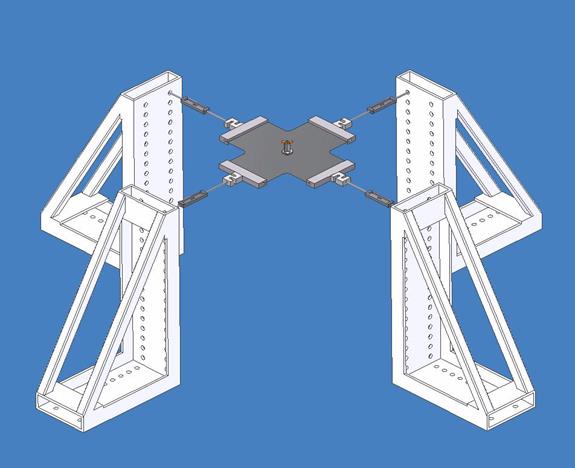
Figure 5: Membrane tensiometer calibration setup. Turnbuckles are used to adjust membrane tension in two directions.
The device should be calibrated in two directions. In use, the principal tension direction can be computed for any membrane tension configuration from the measured component tensions as the direction of the vector sum. A calibration curve, for the example device is computed from equation (9) and is shown below in Figure 6.
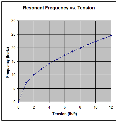
Figure 6: Calibration curve for the example membrane tensiometer.
A close-up view of the calibration setup is shown below in Figure 7.
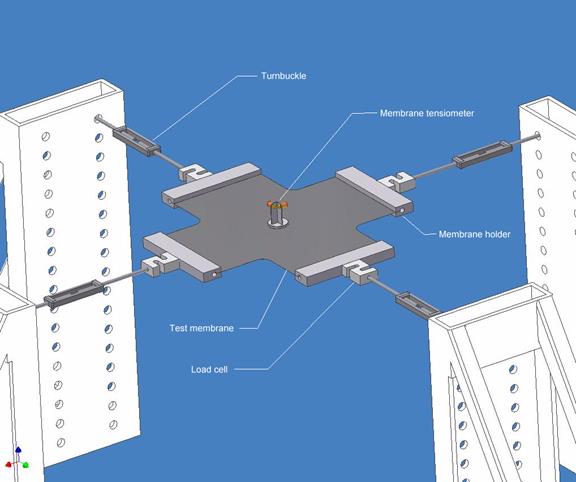
Figure 7: Close-up view of the membrane tensiometer calibration setup.
Opposing load cell force measurements may be used to ensure there is no bending or shear induced in the membrane, or to induce such loads to evaluate their effects.
5 Signal Processing
The two accelerometer analog signals should be digitally sampled at a rate above the third harmonic of the highest anticipated resonant frequency. The digital sample streams should then be each analyzed by a fast Fourier transform (FFT), a standard digital signal processing (DSP) algorithm. The resonant peak of each signal should be identified and converted to a tension measurement by linear interpolation of the pre-stored calibration table.
The X and Y-direction tensions should then be used to compute the principal tension and its direction for each device, as below in Figure 8.
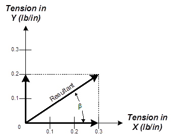
Figure 8: The resultant (principal tension) and its direction (b) are computed from the component tensions.
The signals from several devices can be processed and displayed simultaneously for realtime data acquisition under dynamic membrane conditions.
6 Applications
Unlike the gravity, photogrammetric, and laser speckle pattern interferometry methods described above in section 2, the membrane tensiometer described here does not require that the membrane be horizontal, nor does it require visual access to any portion of the membrane. A single device can be used to measure tensions serially at many points in a tight membrane or many of the devices may be used for simultaneous measurements.
Ground test applications for the membrane tensiometer described here include space deployable antenna mesh tension characterization and measurement of tensions in deployable sun shields or inflatable structures.
6.1 Minimal Mass Version
For measuring membranes with low tensions, such as for a space sun shield, a low mass instrument is desirable. The world’s smallest accelerometer is the Endevco model 22, with mass of 0.14 gram, [3] shown below in Figure 9.
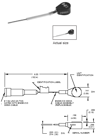
Figure 9: The Endevco model 22 piezoelectric accelerometer has a mass of 0.14 grams (0.00031 lb).
With the Endevco model 22 accelerometer, a membrane tensiometer with a total mass of under 0.001 lbm is possible.
7 References
[1] Ferdinand P. Beer and E. Russell Johnston, Jr., Vector Mechanics for Engineers, Dynamics, Third Edition, McGraw-Hill Book Company, 1977.
[2] Robert D. Carmichael and Edwin R. Smith, Mathematical Tables and Formulas, Dover Publications, Inc., 1962.
[3] Endevco Corp., Endevco Catalog, www.endevco.com.
[4] Don L. Jones, “Membrane Tension Measurement from Gravity Loading,” NGST IOC L425.109.006, September 1987.
[5] Don L. Jones, “Membrane Tension Measurement with a Distributed Weight,” NGST IOC L425.109.007, January 1988.