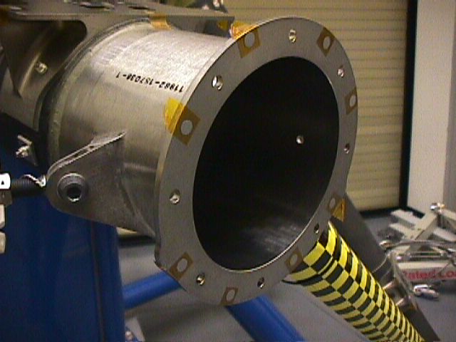
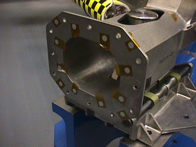
Figure 1: Titanium flanged interface for Astrolink receive antenna deployable subsystem.
The taped dots shown in Figure 1 are photogrammetry targets and will be removed before the installation of the mating aluminum hinge flange.
A drawing of a typical round flange (such as in Figure 1, above) is shown below in Figure 2:
Figure 3, below, shows the tensile load path in a typical flanged joint:
As tensile load is applied to the joint, the flange deflects in bending and the cylindrical sections of the structure come apart, leaving the bolt to carry the load. It is the bending of the flange under tensile load that contributes flexibility to the assembly. When a flanged interface is put into bending (of the longitudinal axis), one side of the flange goes into tension and the other side goes into compression so the net result is an increase in linear flexibility of the bolted flanged assembly (over what it would be if there were no flange as in, for example, a welded assembly).
In space structures, stiffer is generally better. Where flexibility is desirable, as, for example, when tuning a structure to a specific vibrational frequency, it is fairly easy to add flexural elements. But when a structure is too flexible, making it stiffer without adding weight is usually difficult.
Figure 5, below, shows a cross section of the annular pocketed flange assembly with the tensile load path:
The resulting joint is significantly (on the order of a factor of two, depending on flange thickness) stiffer (less flexible) than typical flanges as currently designed. A finite element analysis (FEA) was performed to verify stiffness improvements. Another key feature of this invention is that only one side of the flanged joint needs to be pocketed to benefit from increased stiffness.
For applications that require shear pins to be used for flange alignment, radial lands between pairs of screws may be used without significant loss of stiffness.
 Email Richard dot J dot Wagner at gmail dot com
index.html, this hand crafted HTML file was created December 6, 2001.
Last updated December 25, 2011, by
Rick Wagner. Copyright © 2001-2011, all rights reserved.